Quick update.
I finished the power and ground wiring for the injectors and ignition coils, at least to the back of the engine where I'll splice them into the AEM harness.
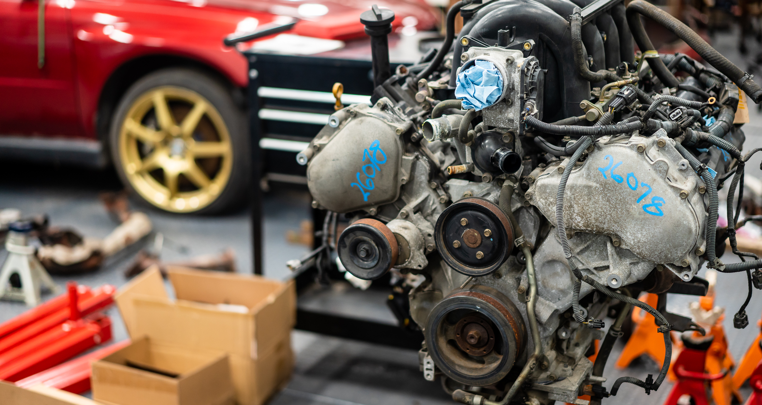
One thing that's been gnawing at me a bit is the drive-by-wire throttle body. I'm not actually going to use it (or drive-by-wire period) on the actual engine build, but I am going to use it to test on the stand. The electronic throttle body has a position sensor in it (obviously), which I will use for this first engine stand tune. I'm going to get it running on an alpha-N tune (throttle position) instead of MAP of MAF because that's what I'll use for the final build (because ITB's).
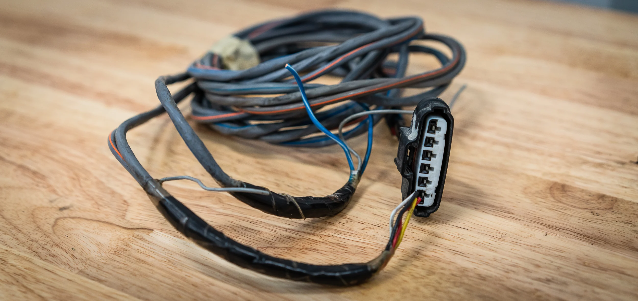
It's been gnawing at me because I've been unable to find good documentation on it, including the pinout of the connector. There are 6 pins. I think because the wires were in their own conduit in the OEM harness, I left myself with a nice long pigtail to work with at least. Yay.
I did find some people guessing at the pinout based on some throttle body swap that the Titan folks were attempting at some point. I used that as a starting point to figure out how this all worked and which wires did what. I'm glad I did find that stuff, as it was correct in identifying the red wire as the TPS (throttle position sensor) ground (!?).
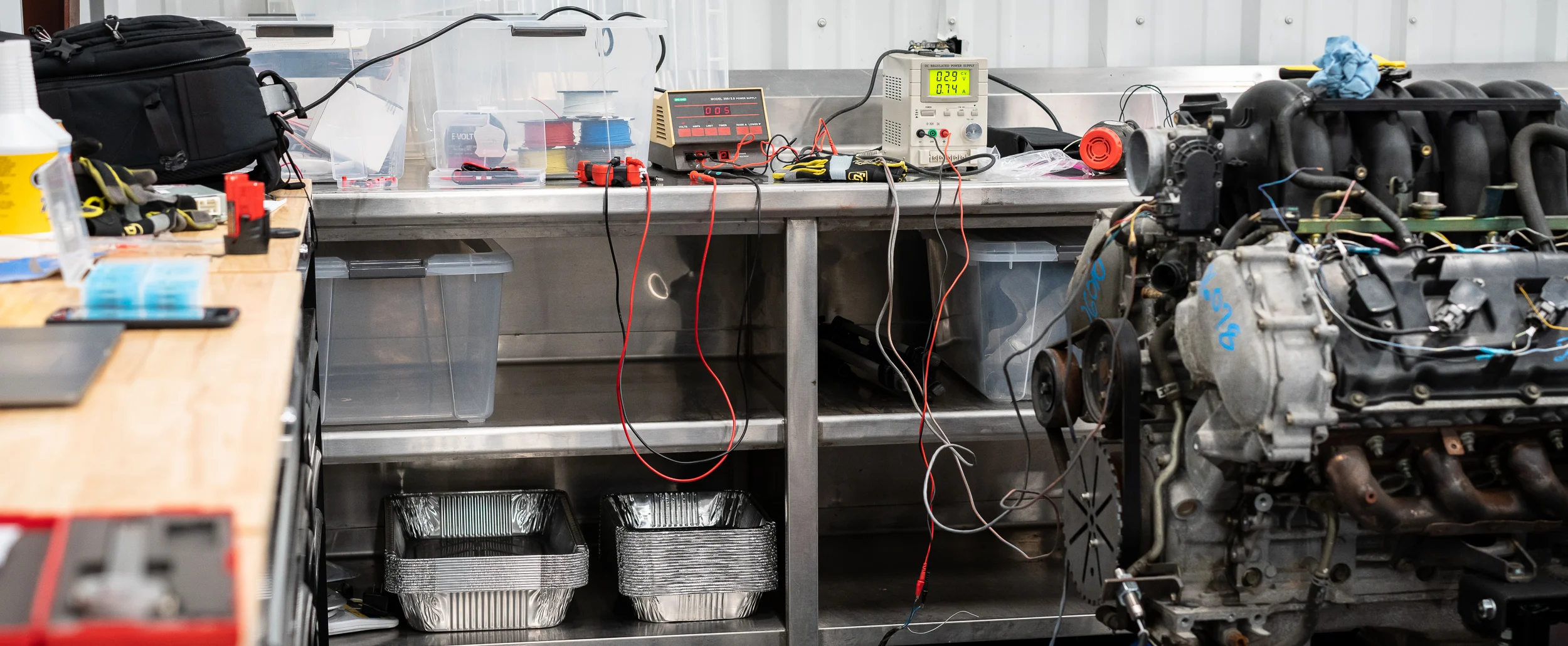
Nik's targeted mass acquisition syndrome has a tendency to be very useful and it worked out yet again in that he had not one, but two, variable power supplies to use for testing. I hooked one of them up to the yellow and red wires (yellow = sensor +5V, red = sensor gnd), then hooked the other up to the two motor wires (blue with stripes), and then hooked up a multimeter to the black and white wires (sensor output voltage).
I fired everything up and got some good readings from the sensor (+3.7V with the throttle plate closed), yay. I started ramping the voltage up on the motor wires and heard a click, but no movement from the plate. Figuring I had the polarity reversed (dbw is usually driven by a half-bridge circuit that uses voltage to open, then reverses voltage to forcibly close), I switched the leads on the motor wires. Again, I got a click but no movement. I pushed the voltage up to 12 then 13 then 14, but the power supply maxes out at 3A, and I still couldn't get movement from the plate.
I thought maybe it needed a bit more current to get the throttle to open initially (then less to keep in position, or close it), so I grabbed a big Schumacher battery charger and set it to the 20A output. Fortunately, it was too smart (we suspect from not seeing a load) and did nothing.
Not to be deterred, I grabbed a spare battery and put the leads right across it. Still clicking, but no movement. At least we knew it wasn't a supply current limiting problem.
I read somewhere that you should be able to move the throttle plate by hand, so I tried pushing myself. No dice.
Only one thing to do then.
Push harder.
With a moderately terrible noise, it broke free and rotated, showing a ring of corrosion that had stuck it shut. Yay! Brute force and ignorance wins again.
We hooked the variable supply back up and sure enough, it rotated open with varying force as I applied more or less voltage. There is a return spring in there as it slowly closes itself when you remove the voltage.
With that, I consider this particular issue solved for now and will move on to the next piece of wiring. I feel better.
Thanks for reading!
damen
Next Datsun Post: Wiring for Cranking + Trigger
Previous Datsun Post: Custom AEM Harness Start
All Datsun Posts: 600HP Datsun 280Z VK56 V8 Project


