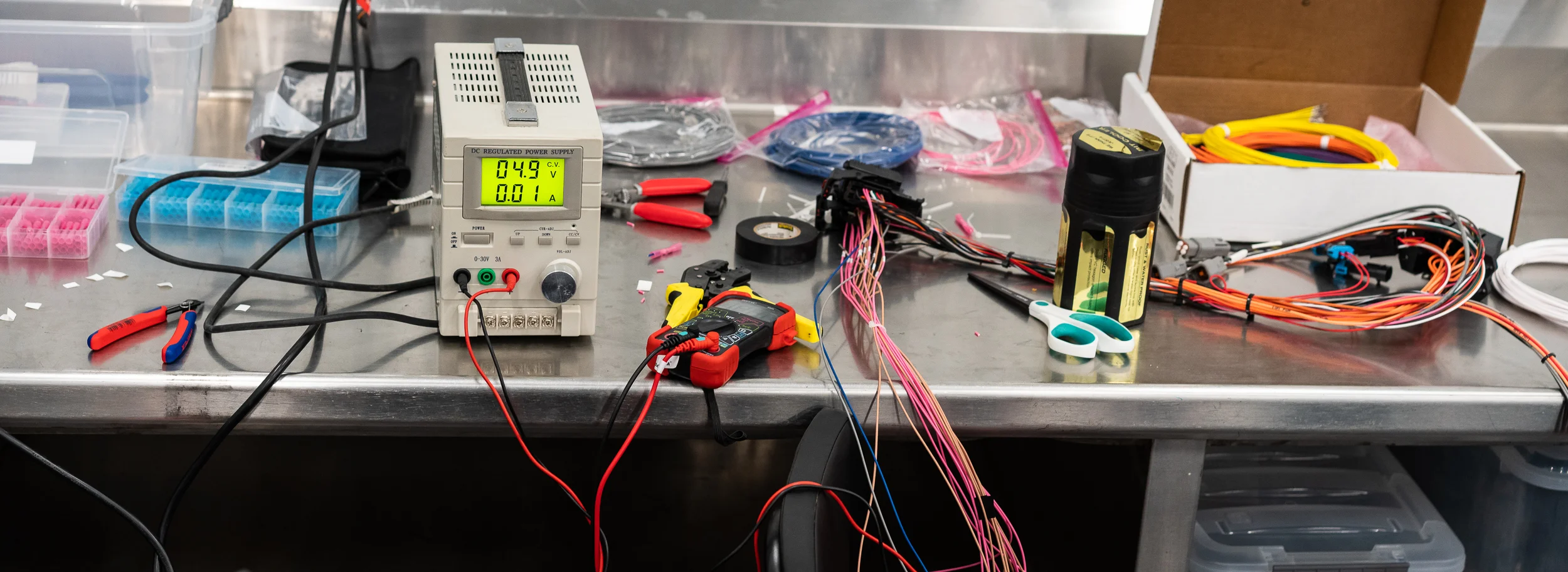
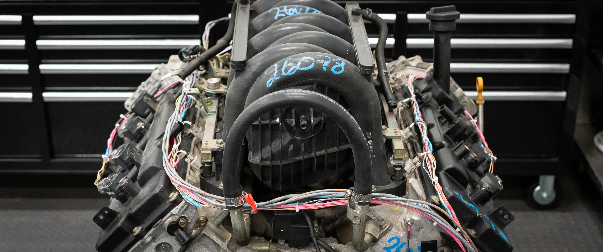
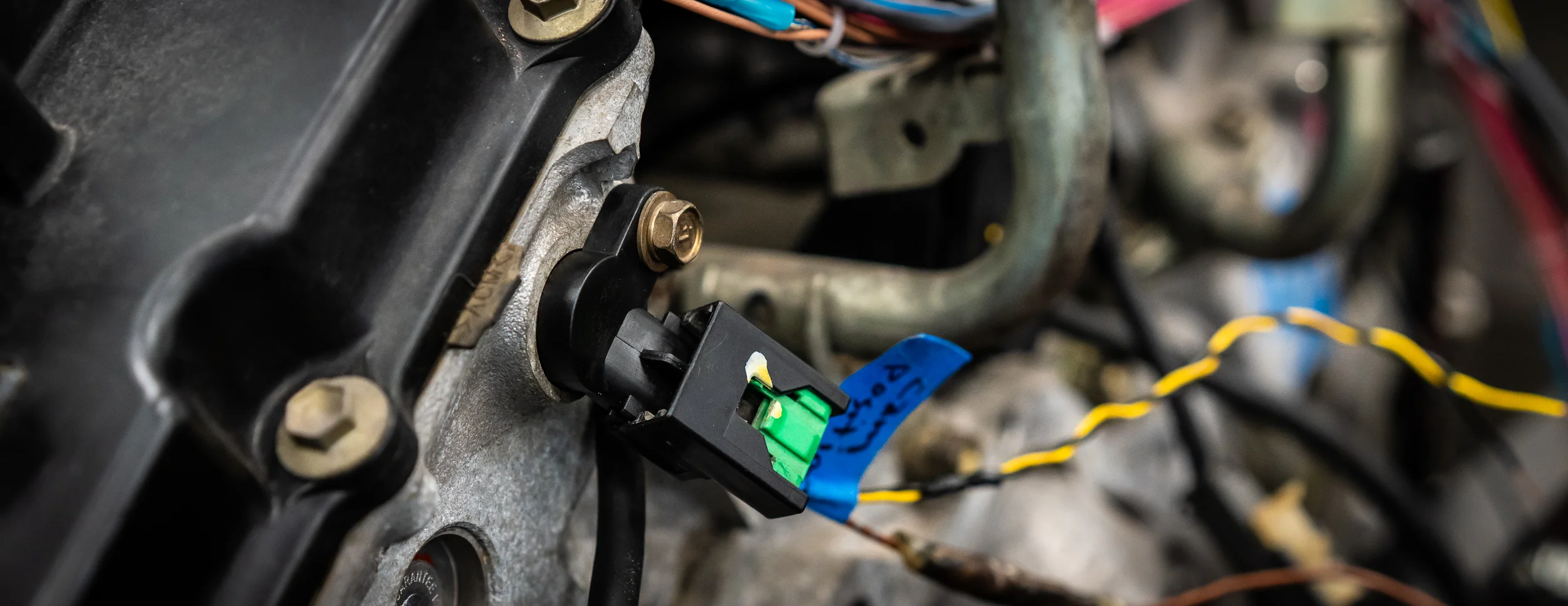
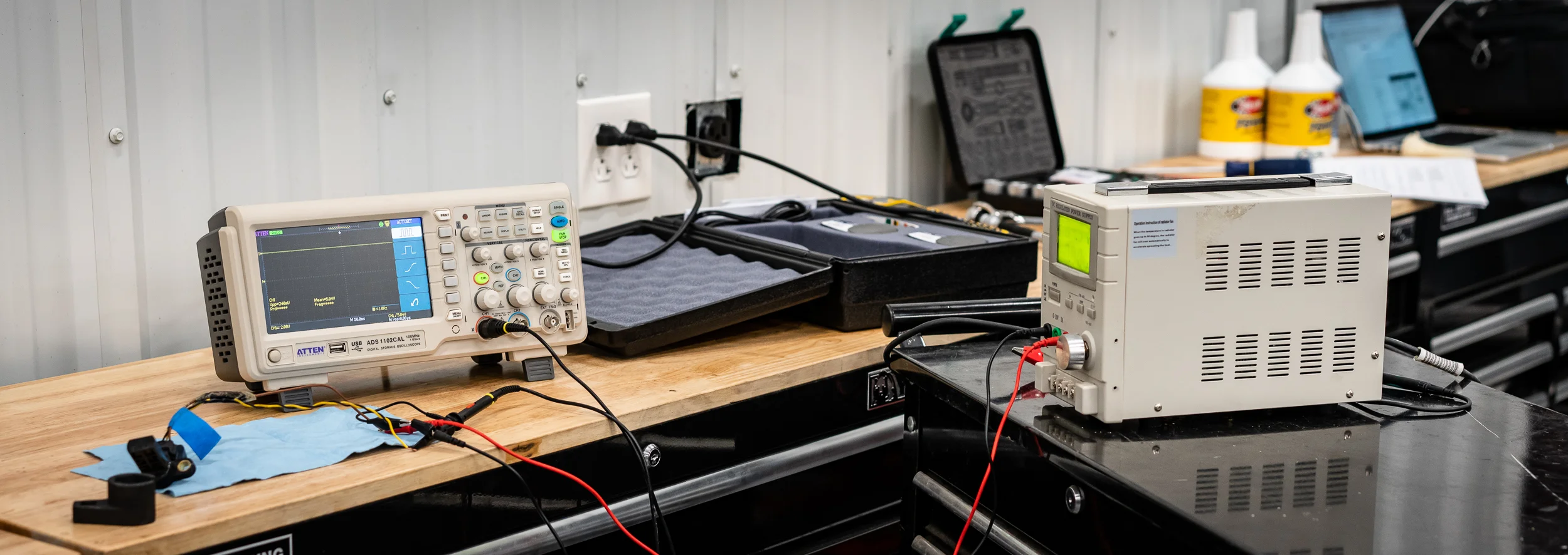
Hold on to your hats, big post here.
I really do hate this trigger wheel. But I'm going to test with it anyway.
It's mounted with only two bolts right now because the bolt pattern in the crank pulley is 6 equally spaced holes (so 60 deg between holes), but the pie plate trigger wheel is 8 holes (45 degrees between). So I'm going to drill two more holes, 180 degrees apart, in the pie plate for a total of 4 mounting bolts.
But before I marked and drilled, I wanted to get the trigger wheel as centered as possible. I measured around the outside with some dial calipers when I bolted it down, but my final check would be to spin it and check with a runout gauge. Quite inconveniently, this junk monster wheel is blocking access to the crank bolt, preventing me from turning it with a ratchet.
Either way, I'm going to have to get the starter wired up, so I figured why not now; at least I'll be able to turn the motor easily, if not very precisely.
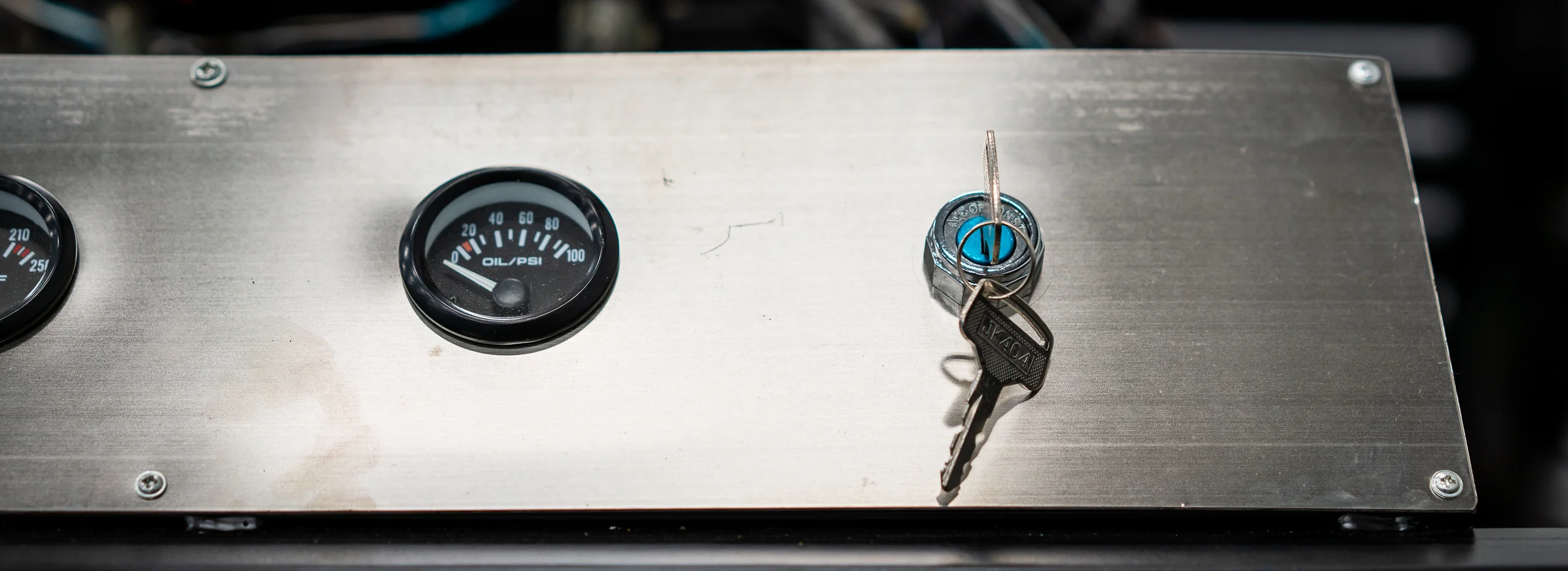
One (neat?) feature of the test stand is a key ignition switch. Why not wire that up?
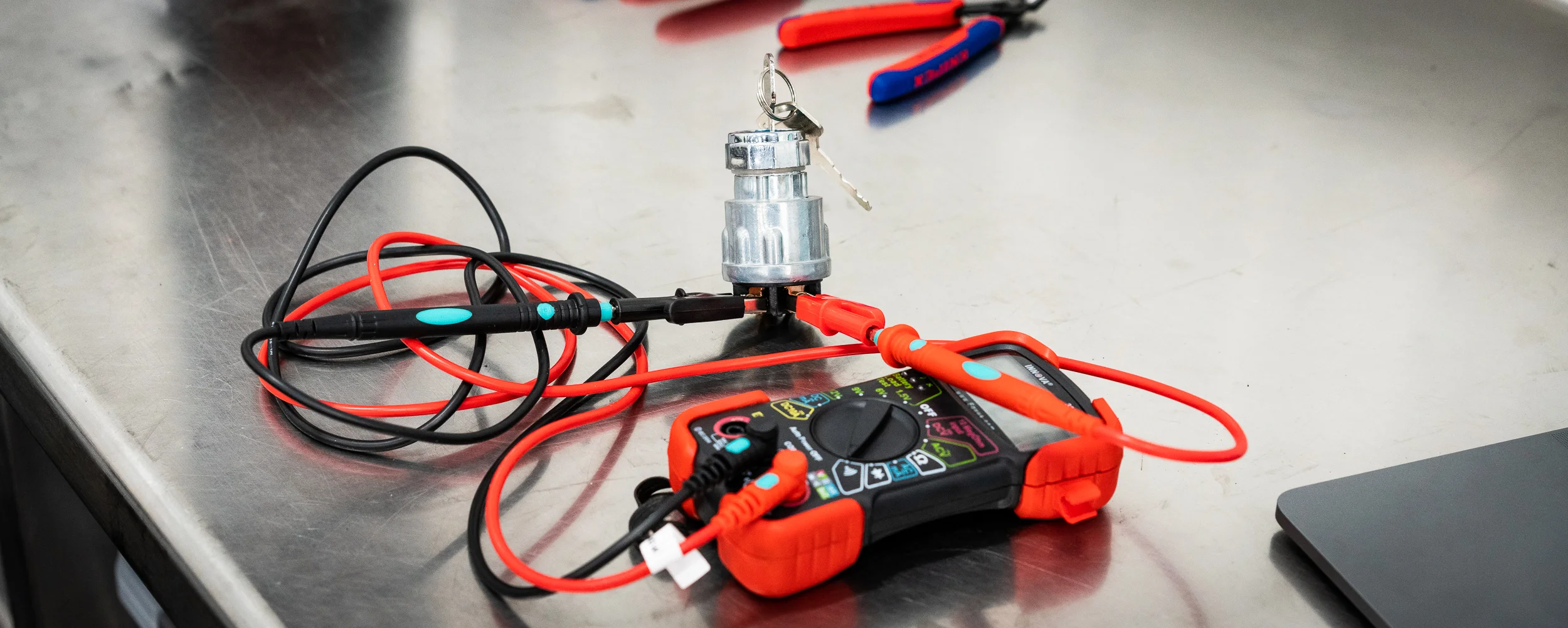
I unscrewed it from its home and put it on the bench to figure out which key positions connected which terminals on the back. I was happy that it was all quite deterministic.
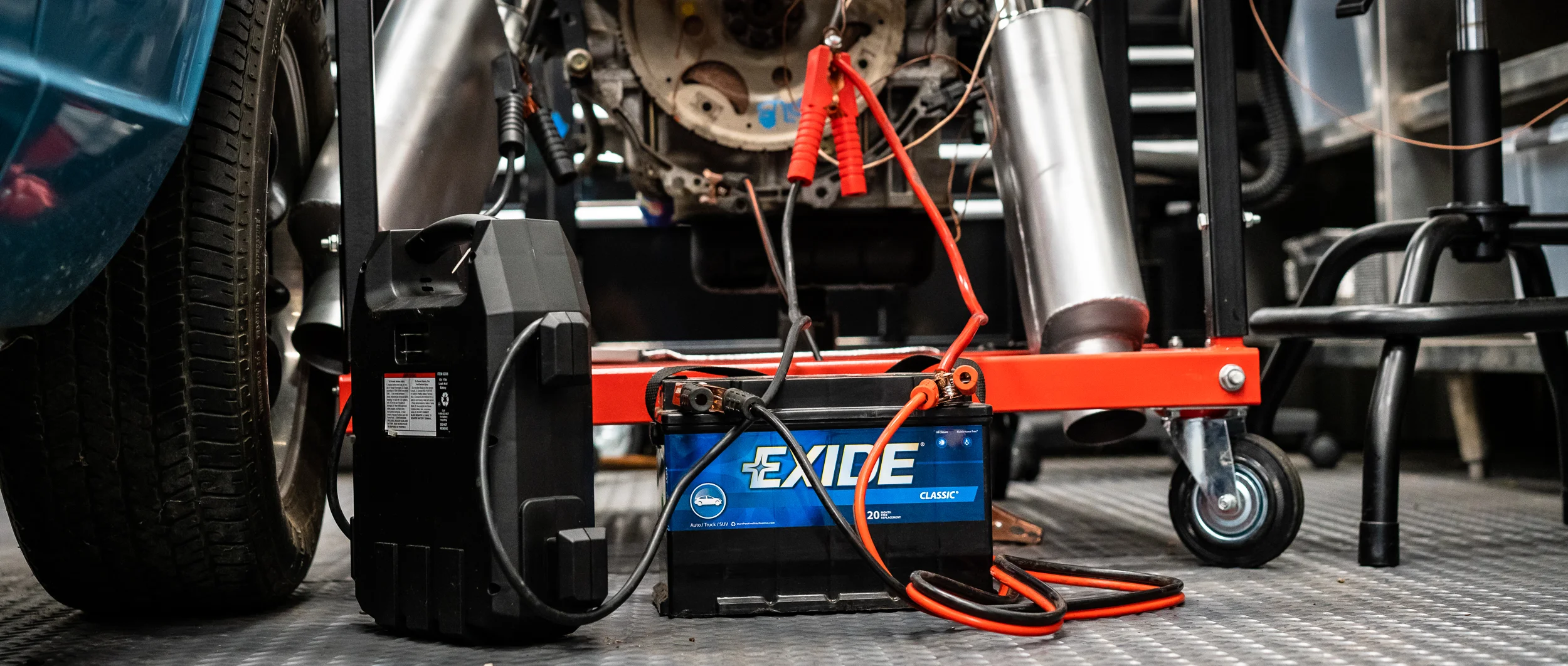
So I wired it up to the starter solenoid and hooked up some battery jumper cables to the starter to get it to spin.
Annoyingly, the starter seems to need a super beefy connection to get it to move. I would turn the key and you could hear the solenoid fire, but no spinning of the engine. I even uninstalled the trigger wheel to turn the engine over by hand to confirm it wasn't seized or anything. It wasn't.
Eventually with some different jumper cables from a jumper pack, it spun the motor just barely and then the jumper pack died. I'll order some proper battery terminals so I can ensure a good connection for next time. I wasted a lot of time on this issue.
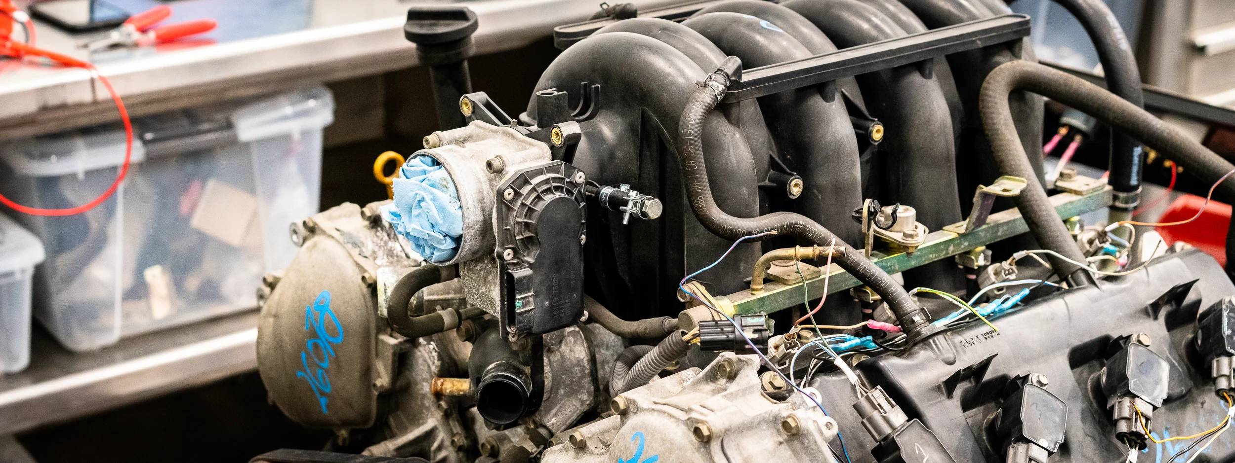
I wandered around in circles (pensive lapping?) for a bit, trying to figure out what to do next. I randomly capped an open manifold port.
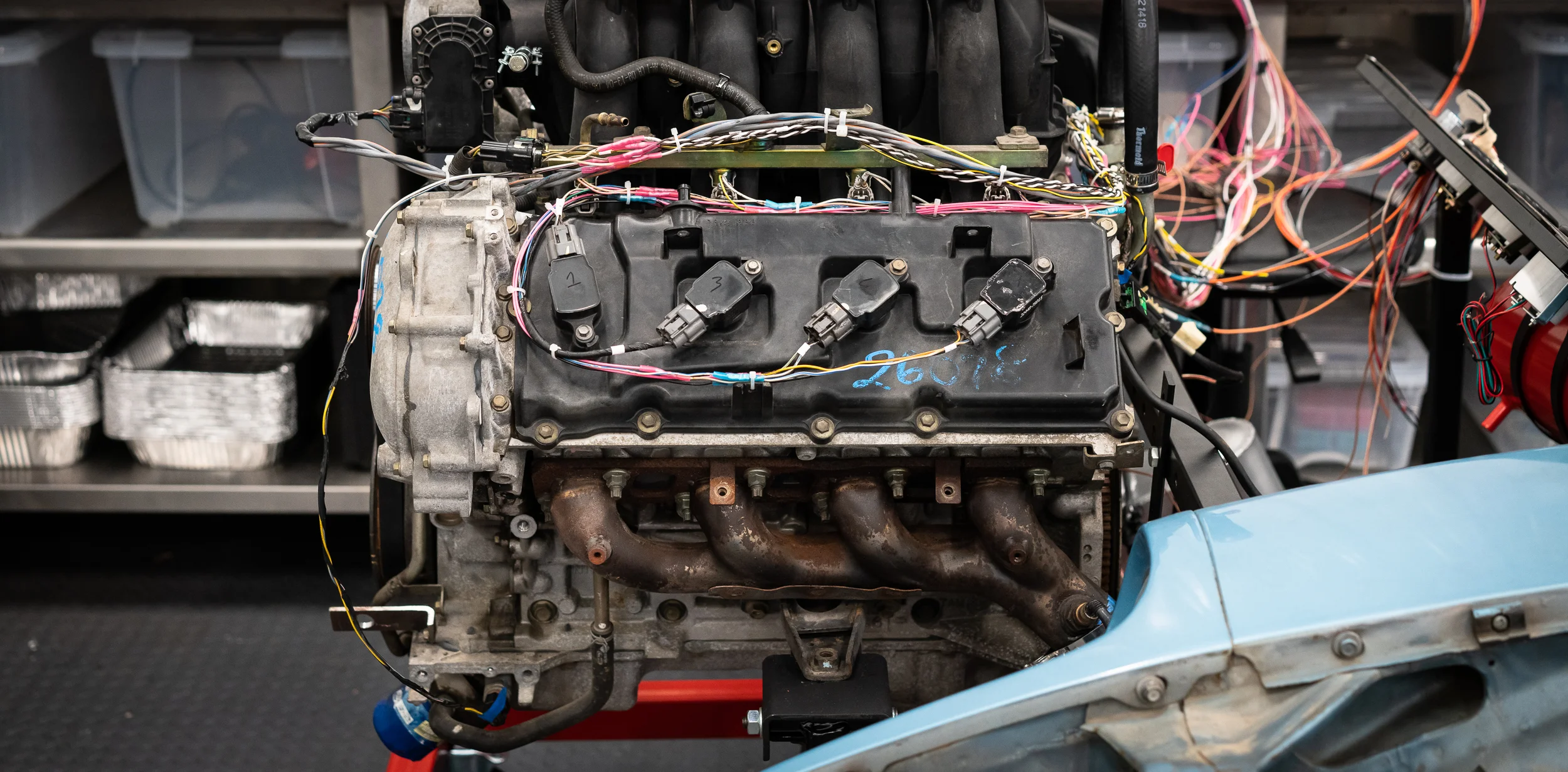
I then decided that what the hell, why not just start wiring the harness to the engine and get on with it. So I did.
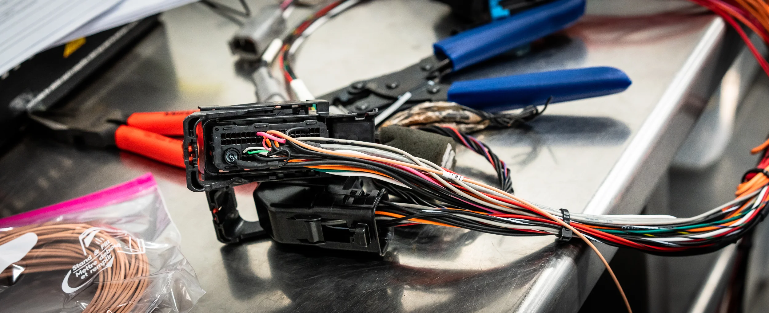
Behold, the first connection of the actual ECU connector to the actual engine:
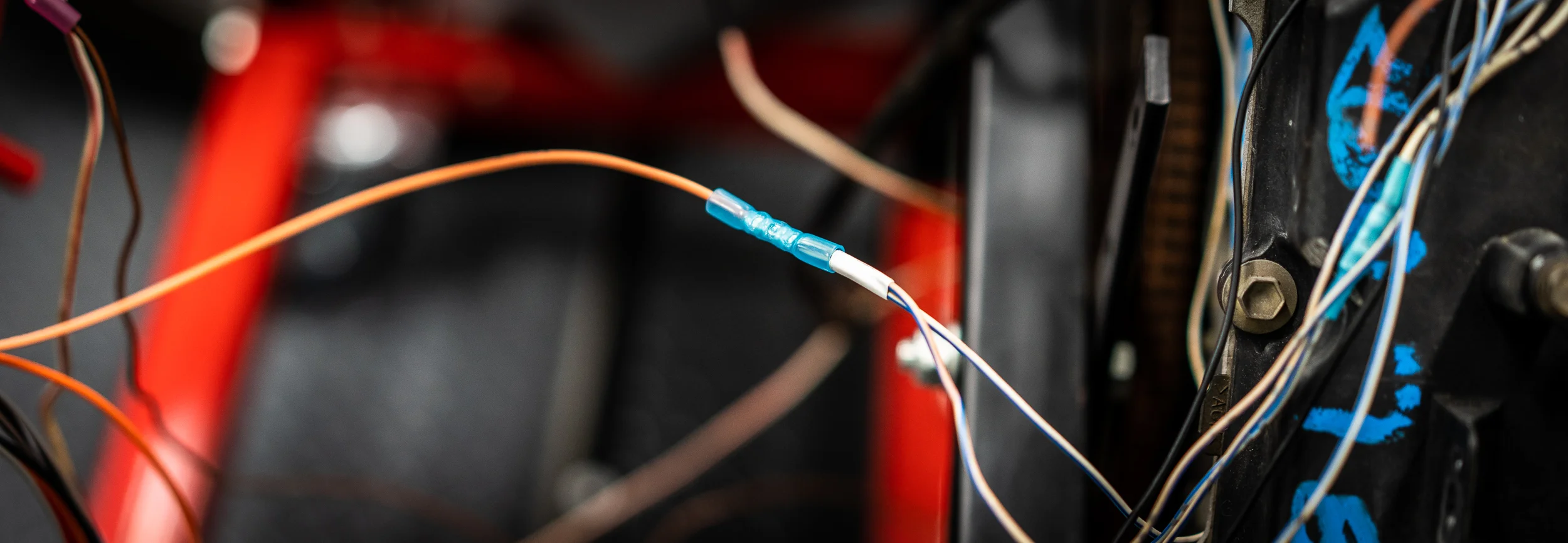
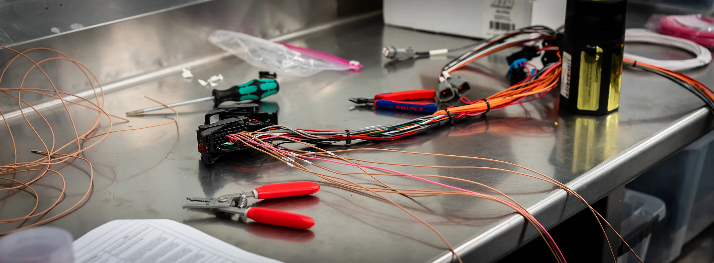
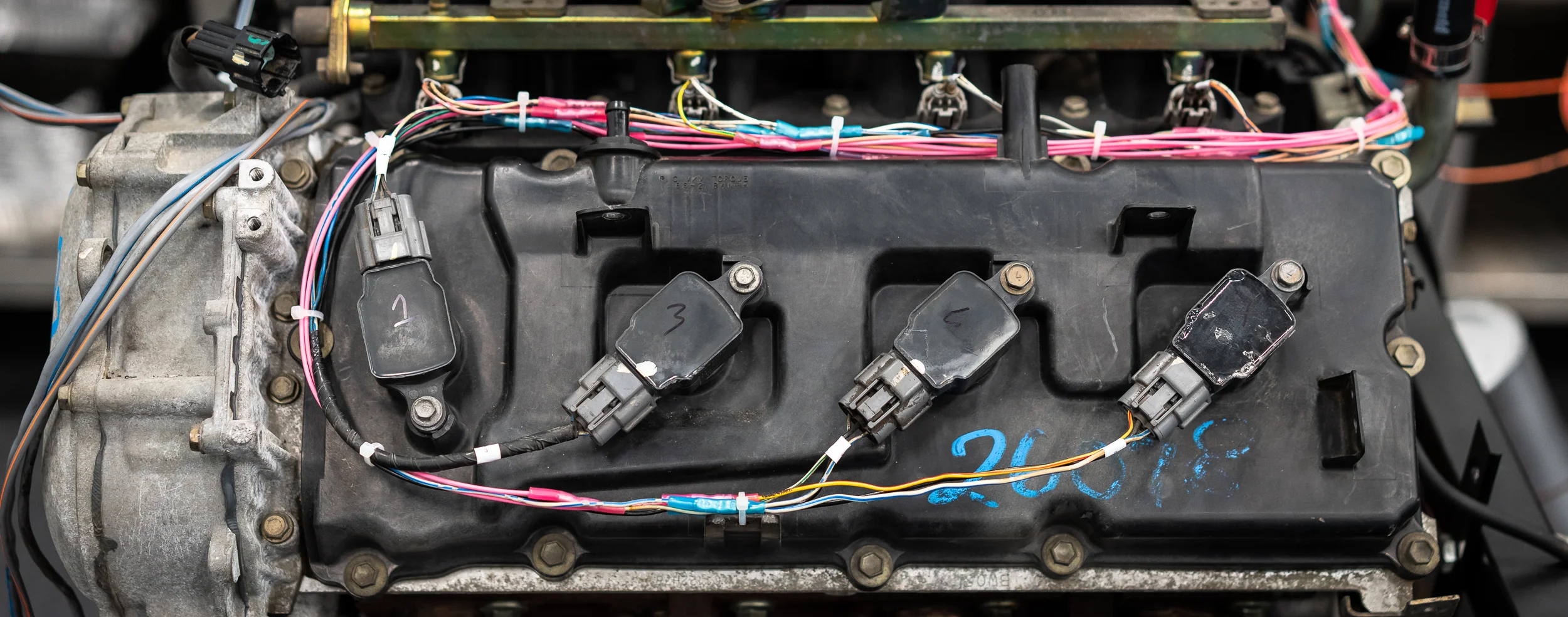
I started running the injector signals next, and it looks like I have enough colors to do each one in a different color.
Is that the right way to do it? The super professional way seems to be use all white for everything. I'm not pro enough for that, so that's out. Then I've heard of grouping all the outputs into one color, inputs another, ground and power another, etc. I'll see how I like this and adjust for next time. Either way, I'm labeling both sides of the wire.
You can see the first injector signal wire run here.
It's the light brown one with the "INJ1" label.
I printed a bunch of labels and then realized I was late and needed to leave. So here's a pile of labels.
I'm not crazy impressed with this labeler. The print is not super solid (it looks a bit faded in spots sometimes, like a printer running out of ink), and it wastes a huge amount of tape, as you can see. This everything-proof vinyl is about $0.90 / foot, which I'm not sure is expensive or cheap? I should try to mess around with different settings to see if I can waste less tape.
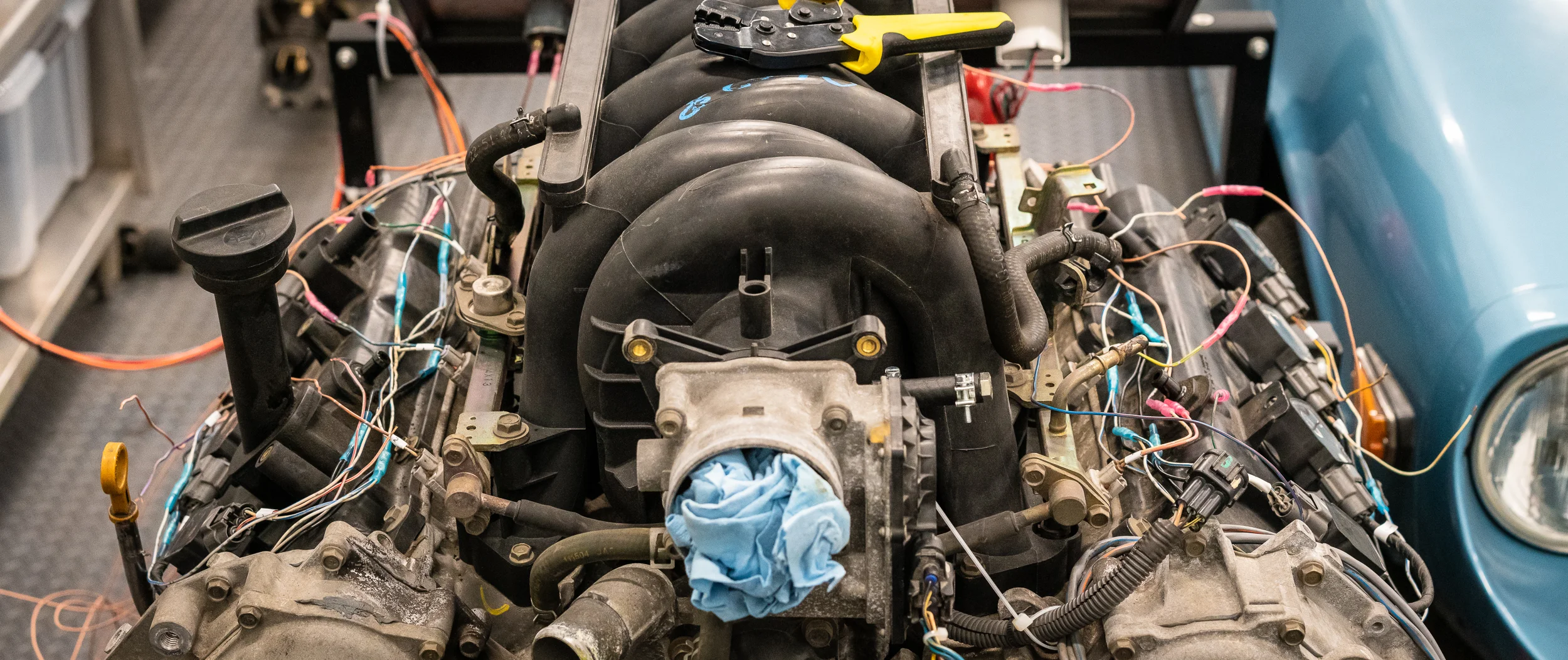
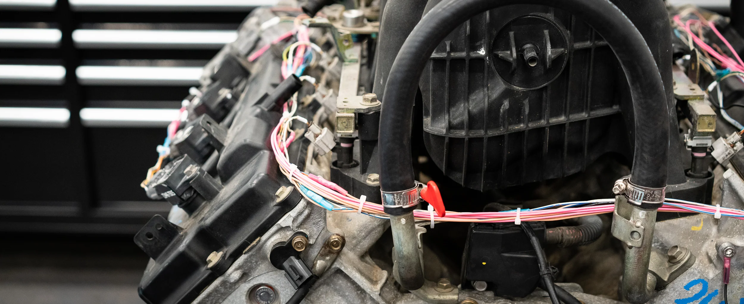
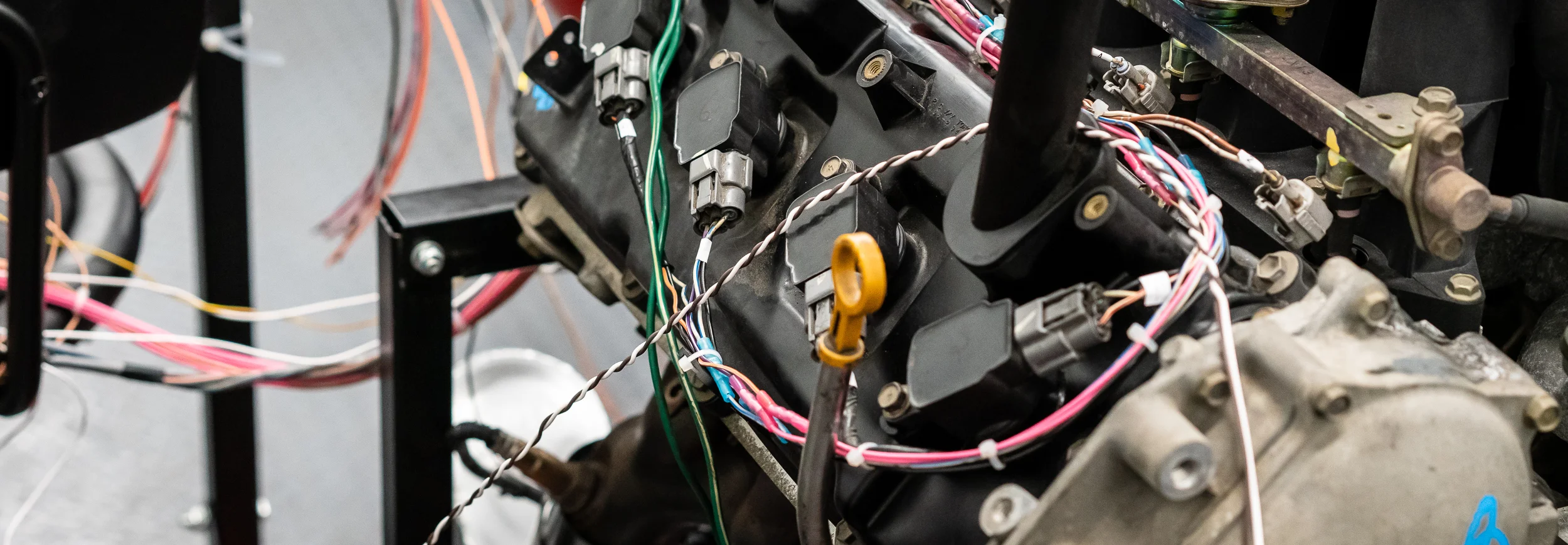
Moving right along, I started hooking up the signal wires to the injectors and coils.
So here's something that I messed up:
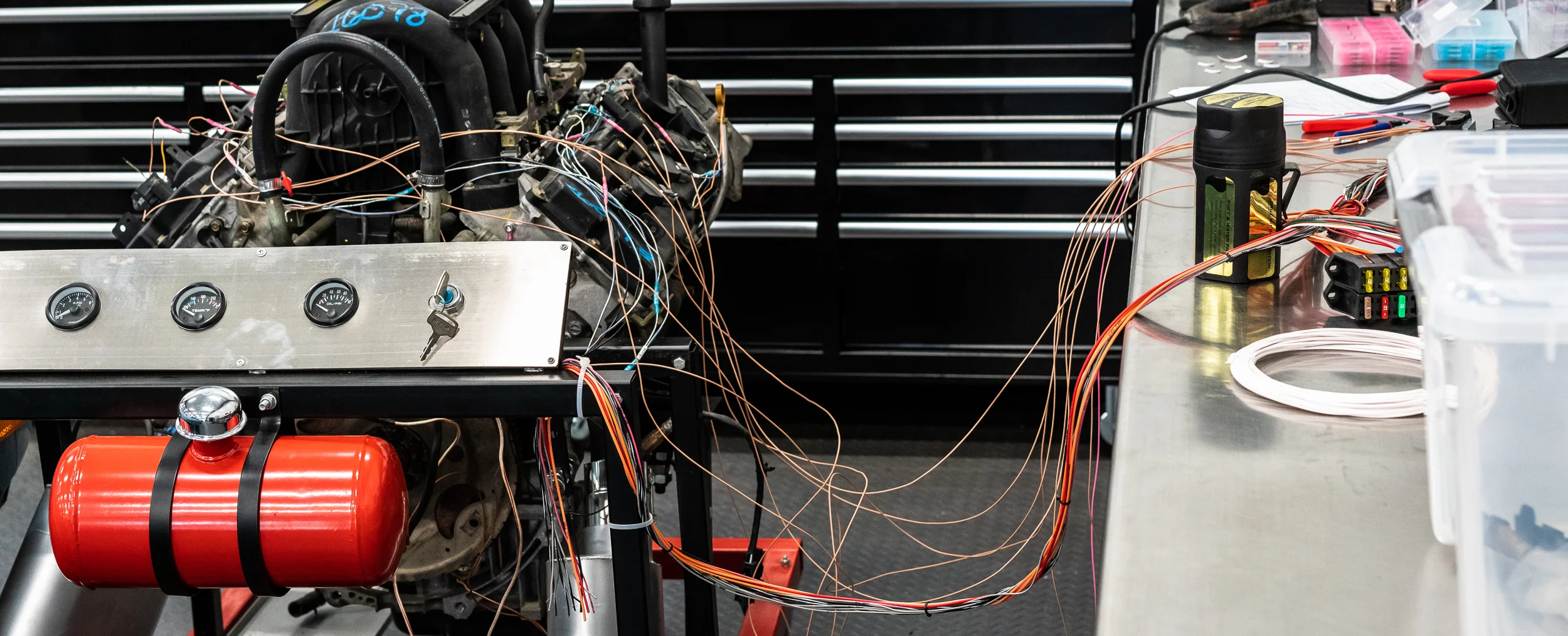
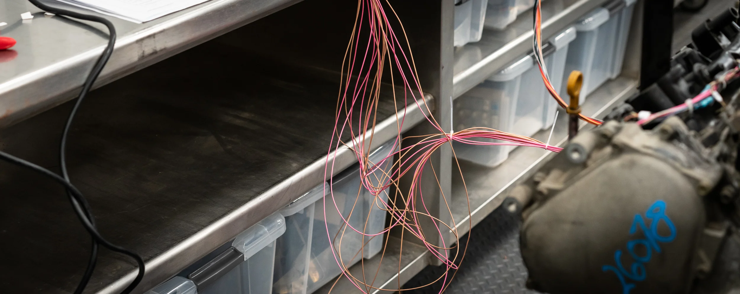
I didn't really know how long to make the harness, so I just used the full-length 8' pre-terminated wires that came with the mini-harness. Obviously, that meant I would have slack in some wires and not in others. I didn't think it would matter and I didn't think it would bother me.
Whether it "matters" or not remains to be seen, but I was wrong about the bother. It's horrible and driving me nuts. I call it my 'Spaghetti of Shame'.
Urg. I can see myself de-pinning all of these, cutting to the proper length, and crimping on a new pin. I was actually gonna start that, but the de-pinning tool needed to extract the wires from this MX123 connector is 0.025" in diameter(?!). A paper clip is too big.
And the special tool is $70.
I ordered some 0.025" drill rod from McMaster Carr for $1.75. We'll see if I can make that work, but in the meantime, it's a big ol' bowl of spaghetti for me.
Shame.
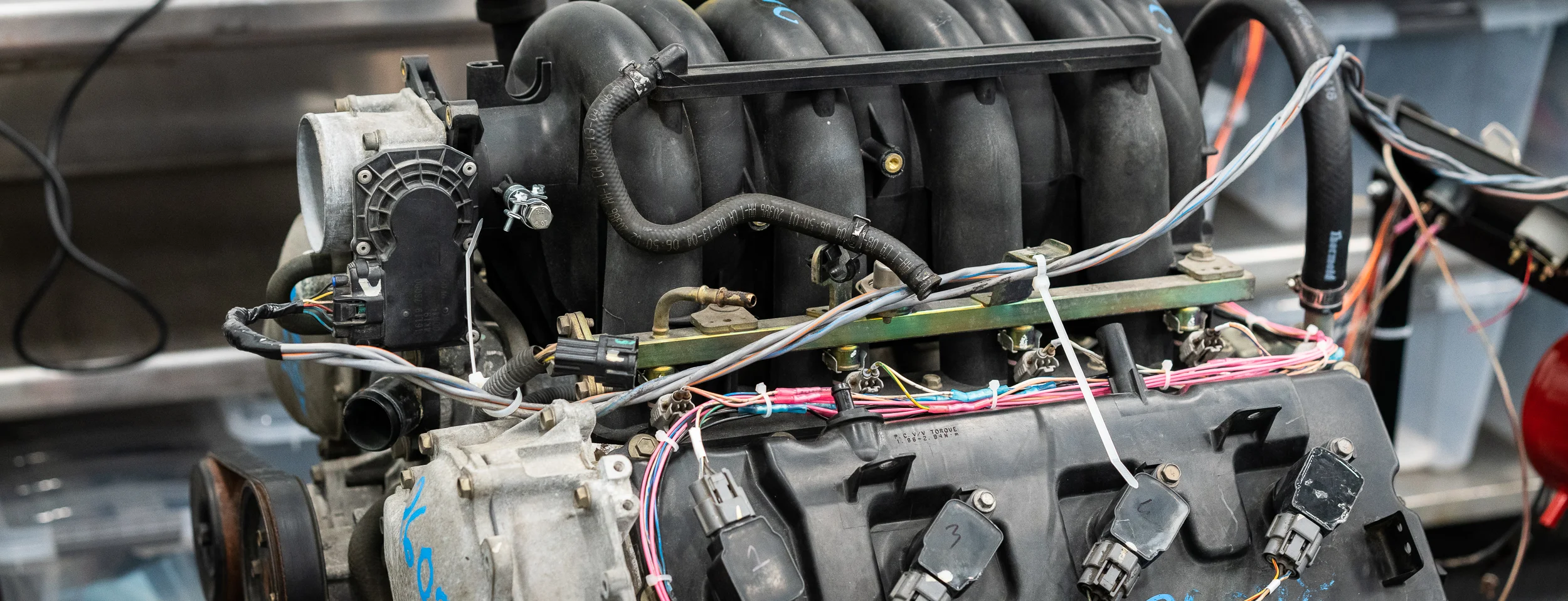
Other than that, I'm reasonably happy with how it's tidying up.
With the ignition and injector signal wires complete, I decided to wire up the throttle body next, keeping the shielded conduit in place and routing where it seemed appropriate.
As I was starting to connect the wires into the ECU connector, I realized that some of my measurements from the reverse engineering session previously made no sense. At some point I'd come up with a negative voltage for the throttle position sensor. It took some googling around and a tip from RYEphil and some more power supply work and pushing the throttle plate around to realize that the two wires from the TPS were the same signal, but inverted. So I chose the signal wire that gave ~0V when closed and ~5V when opened to hook up to the ECU. The ~5V open / ~0V closed signal wire was terminated and capped.
Hopefully that's the right choice?
Once that was sorted, it was smooth sailing to finish the throttle body wiring (DBW motor and TPS) and route it nicely.
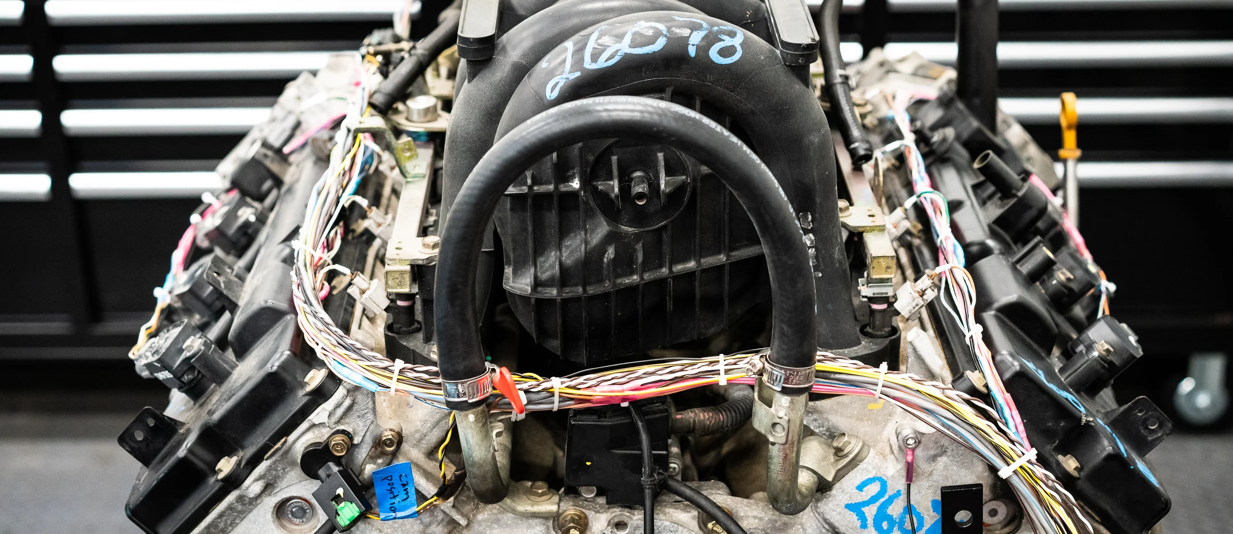
In the bottom left there you can see the cam position sensor (which is a new part that I installed). It's 3-wire, which I take to mean a hall-effect sensor. However, the wire colors were not fully conclusive, although two twisted together with a third being thicker and separate were good hints.
I wanted to make sure I was hooking it up properly, which means testing. Which means I finally got to use a tool I bought almost 6 years ago and has been waiting patiently in a box on the shelf!
Ye Olde Oscilloscope!
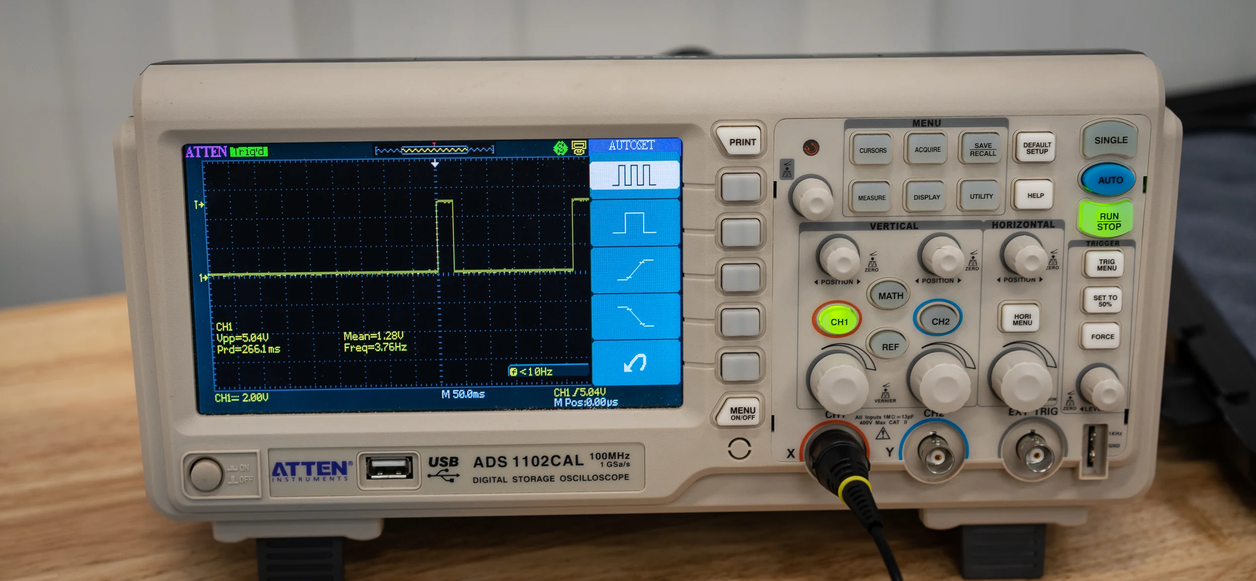
With the power supply set to 5V (although I think anything from 5 - 12V should be okay), I clipped on some power and probes to the wires (black = gnd, yellow = signal, green with silver dots (?) = pwr) and pulled a random ferrous tool out of my drawer. An O2 sensor wrench in this case.
I did my best to wave the tool around really close to the sensor to see if anything would come out, confirming this particular pinout.
Behold, a signal!
Literally from handwaving.
I was satisfied that this wiring was right, so I re-installed and wired it in. Yay.
I figured since I had the scope working and setup, I should test the cruise ship crank trigger sensor that I picked out of the Mouser catalog and see if it made any waves.
The crank trigger sensor is a 2-wire VR sensor, which RYEPhil tells me is better than Hall for this application because, amongst other things, Hall sensors generally don't do 9,000rpm very well. I'm not sure I'll make it quite that high, but I definitely will be over 8k and the head room sounds nice.
I clipped on the probe and recommenced hand waving.
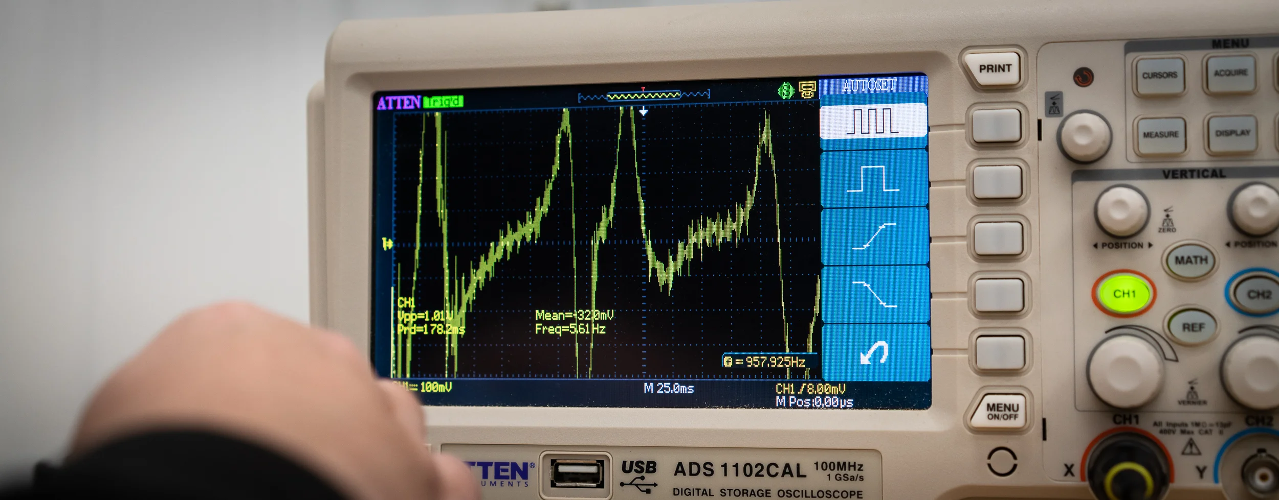
Behold, another signal!
It's analog, obviously, and requires a bit more processing from the ECU compared to a Hall square wave, but the AEM Infinity can take either. Stay tuned to see if this works.
Next.
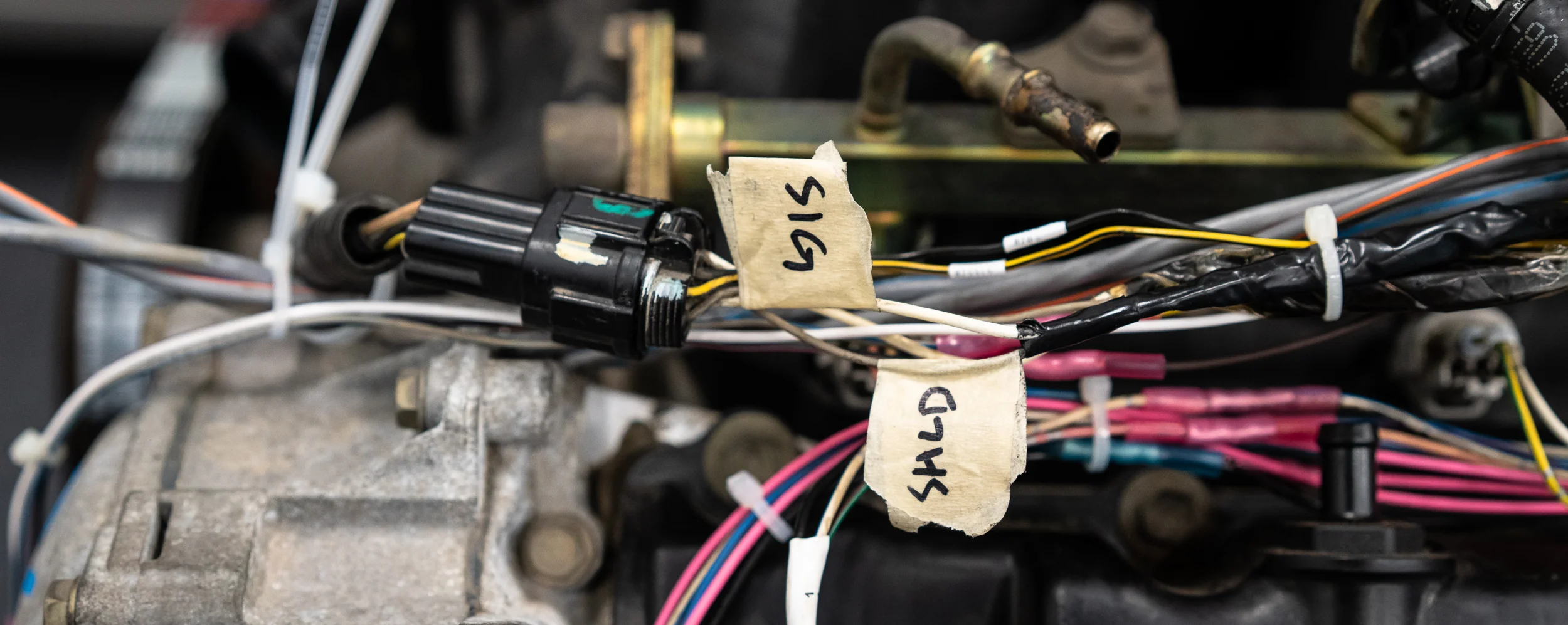
There's a connector that leads into the V underneath the manifold. It has 6 pins: 2 for water temp, then 2 each for the 2 knock sensors. Fortunately I labeled it nicely when I disassembled the OEM harness. The water temp was quite straight forward- one to the signal, one to the sensor ground. Easy.
The knock sensors, on the other hand, start at the connector as 2 normal 20awg wires, then are turned into a shielded single wire cable. Here's what the cross section looks like for that:
The way to splice shielded cable involves peeling back the shielding, butt splicing the inner wire, heat shrinking around the inner wire, then putting the shielding back and using a heat shrink solder sleeve over the top.
Yeah, that's gonna be a no for me, dawg.
So I clipped off the shielded part and twisted some pairs by hand to see if that works. There's a 99.9999% chance this won't be used for this idle-on-a-stand test, but I wired it up anyway. For completeness or something.
I've been dreading messing with the crank trigger wheel, mostly because I just don't like it.
But it needs to be done. Step 1 is to get it centered.
What could possibly go wrong with that?
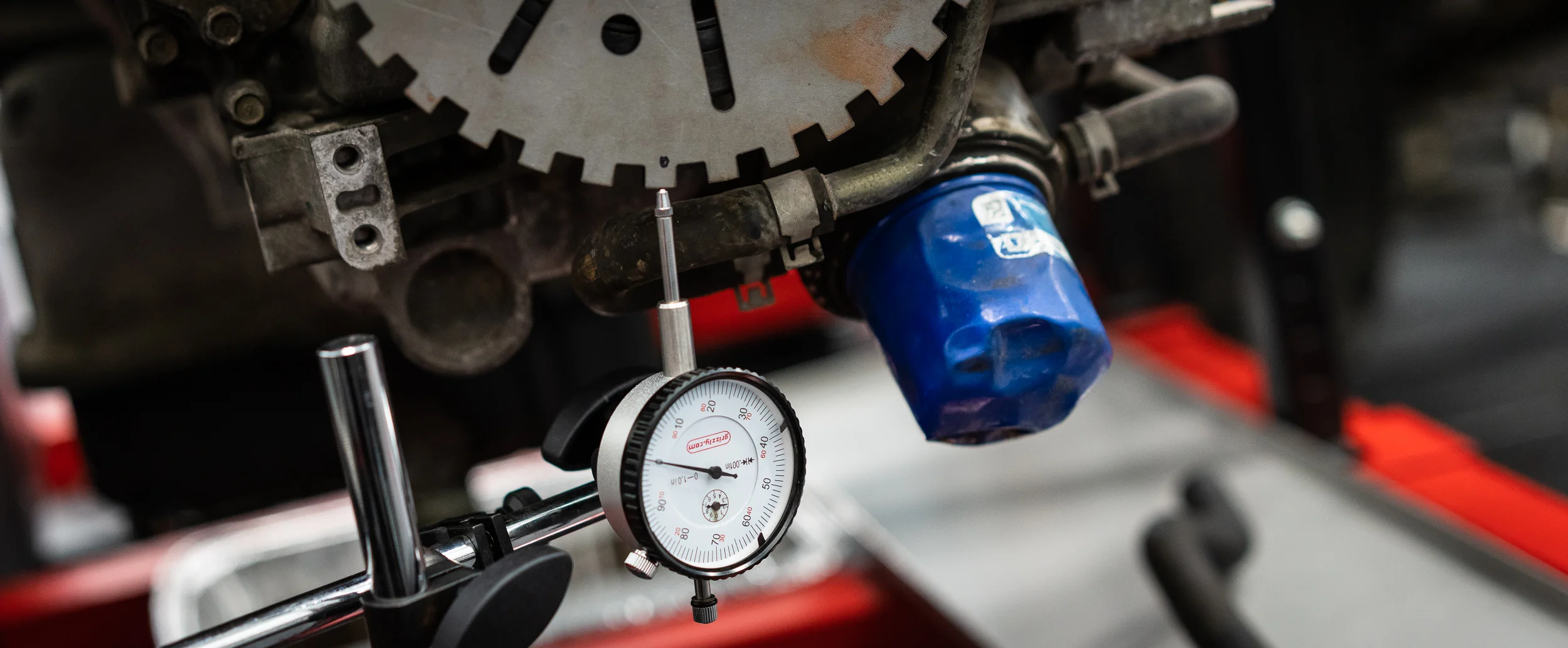
I have this Grizzly dial indicator and it's terrible. The mount is terrible. I don't like it. I was gonna measure, turn the motor a bit, measure, etc.
I gave up on that quickly because the whole gauge setup was unstable and unrepeatable.
Next.
I finally decided to center the trigger wheel as best I could with dial calipers, then setup my camera and film the gap between the sensor and the wheel as I turned the starter. What could possibly go wrong?
Well, for starters (heh), I couldn't get the engine to turn over on the starter. Yep, same problem as previous. Bad connections? Bad wires? Bad operator?
Do not try this at home.
I got it to turn using a battery and a jumper pack in parallel, stacking the alligators and all that. It was lame and did not feel safe.
Nik came to the rescue and gave me some fancy battery terminals to borrow and I found the OEM starter cable that looks one step thicker, so I hooked those up.
Oh, and I tightened the starter bolts, which were quite loose for some reason.
Much better. It cranked over really nicely.
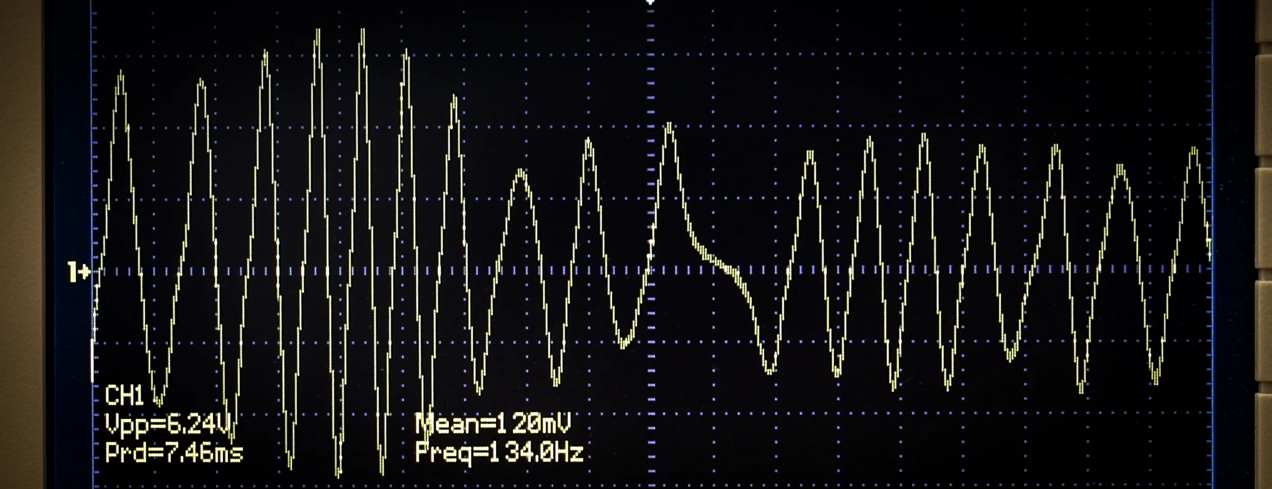
With the starter spinning when I hit the key, I was able to record some video of both the trigger wheel to sensor gap, and the signal on the oscilloscope. The scope can log data somehow, but I'd need to spend time with the manual for a bit.
Anyhow, here's the gap at about 0.015".
The wheel was off center a bit, so the gap was varying between 0.010" - 0.040". However, the signal looked pretty nice! I'm pleased.
You can see the missing tooth right around the middle there; this is a 36-1 wheel.
Then you can see the amplitude of the wave change as the gap changes. Smaller gap = higher amplitude.
Anyhow, good enough for me, so I re-centered it so the variance is less than 0.010" now, and tightened it down.
Next.
Thanks for reading!
damen
Next Datsun Post: Wideband Sensors
Previous Datsun Post: Sorting the Throttle Body
All Datsun Posts: 600HP Datsun 280Z VK56 V8 Project

