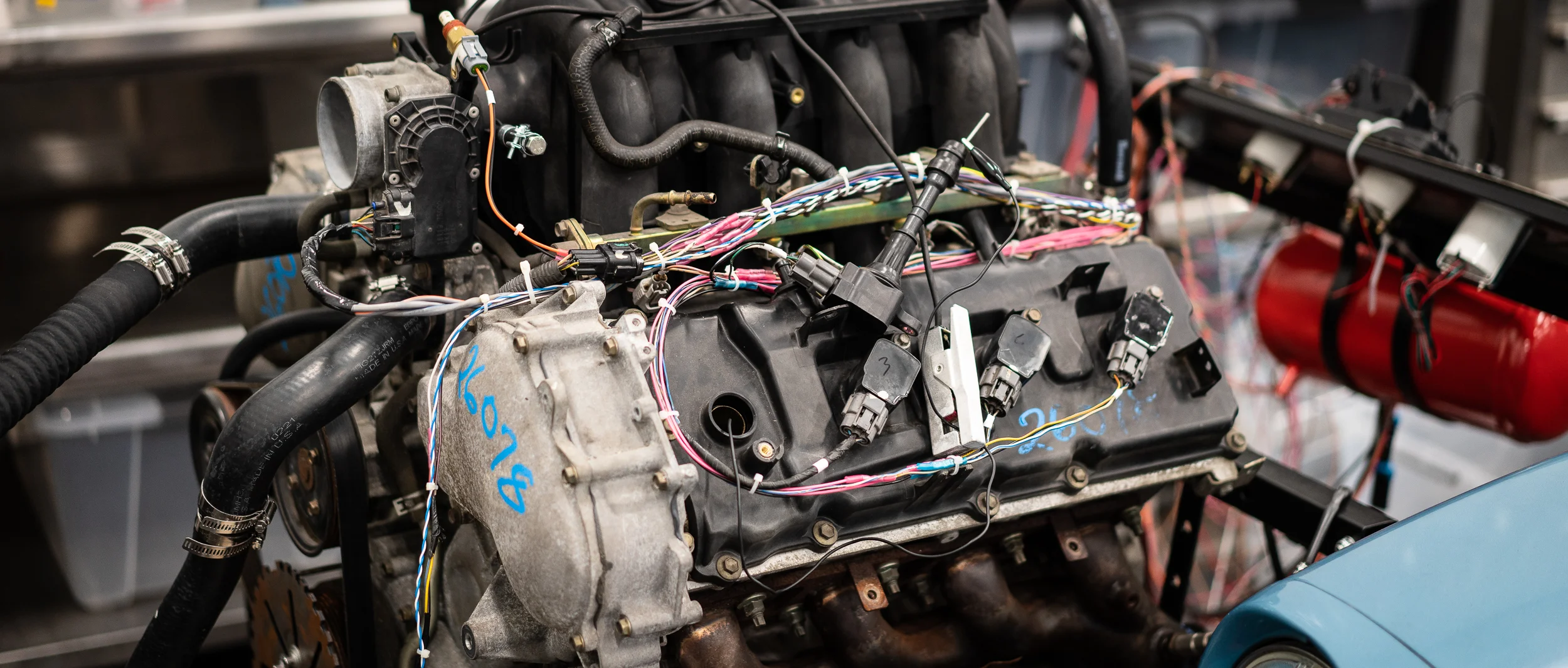
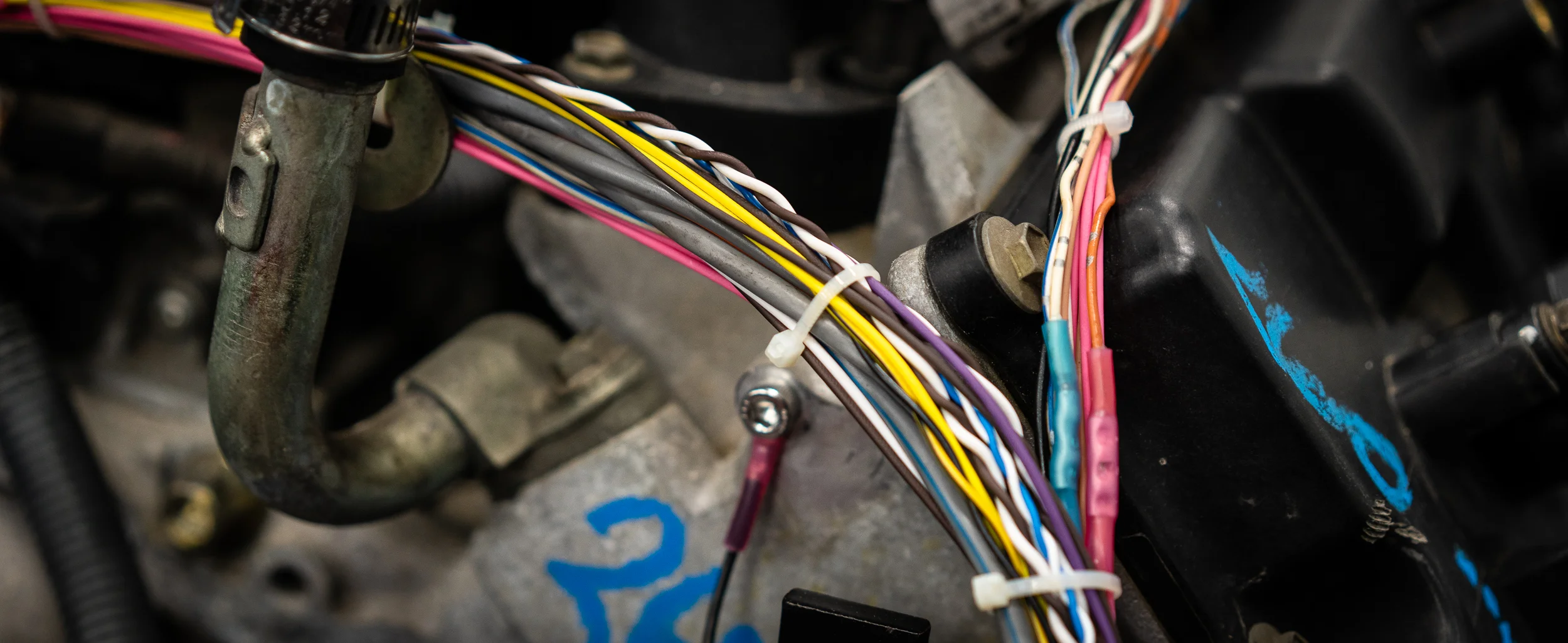
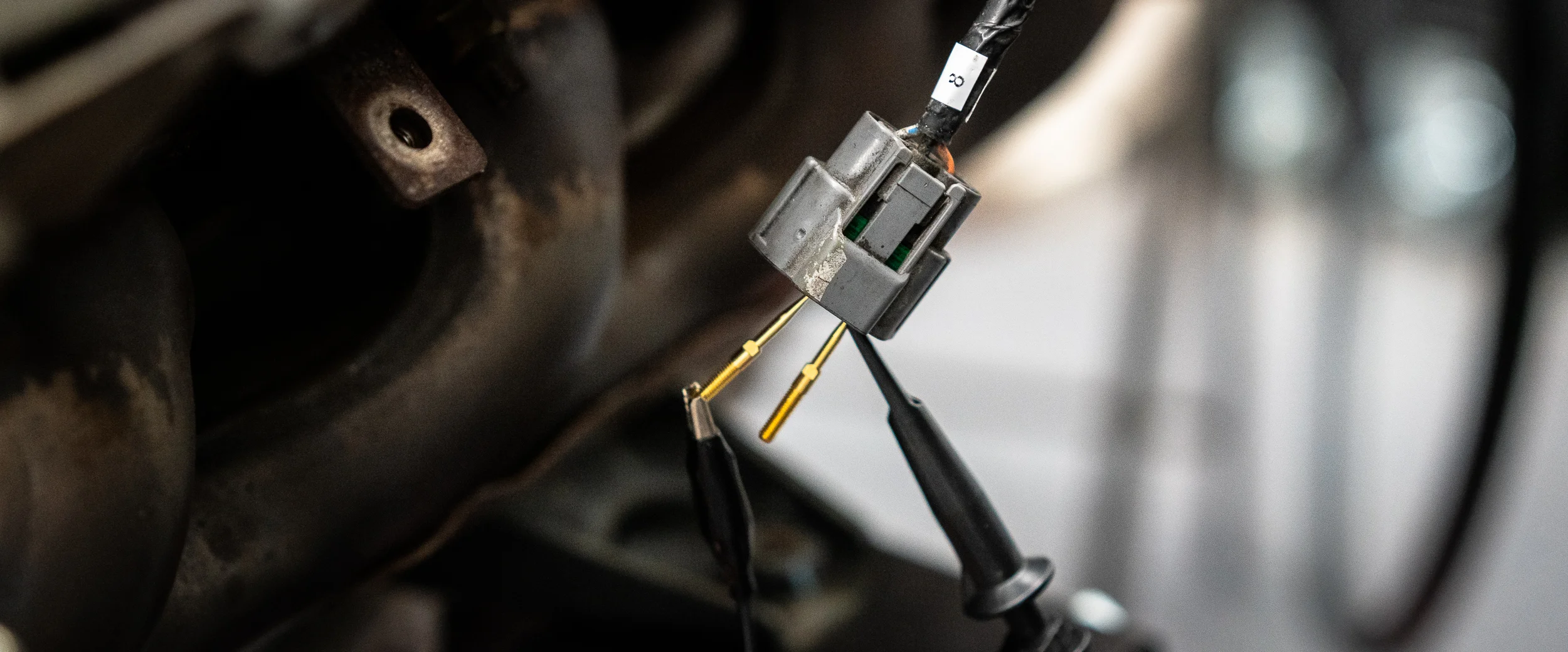
With the wideband sensors plugged in, I only had one sensor left to add in: the accelerator pedal position sensor.
Well, I don’t have the stock Nissan Titan pedal setup, which has the pedal sensor in it, so I jumped on eBay to see what might work as a replacement.
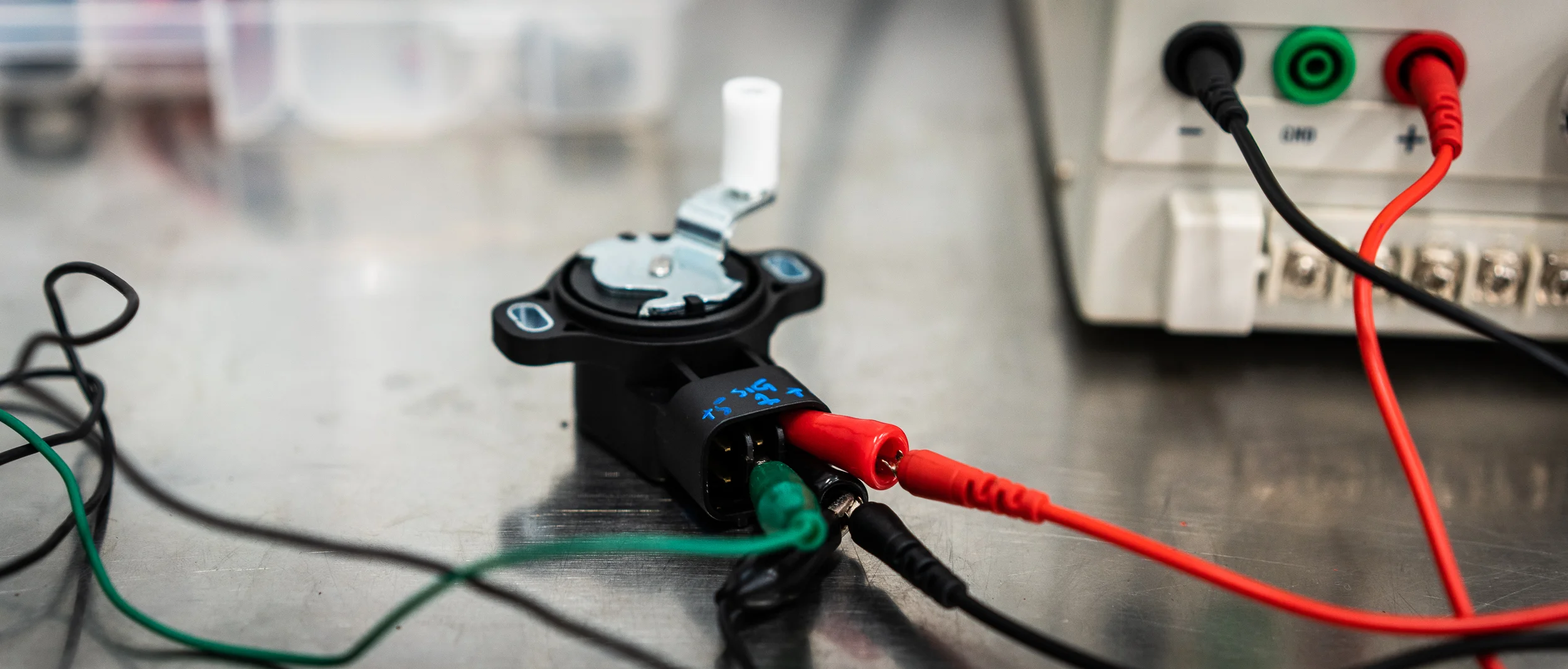
My favorite find was actually a Chinese replica part for a Nissan 370Z (keepin’ it in the family!), so I ordered one for $17. It’s unique in that it has a little actuator arm with a bearing on it that I can use to rev the motor. Lots of the other sensors didn’t have such a nice mechanical portion. In the meantime, I found a couple images online with some hints to the pinout, but nothing solid.
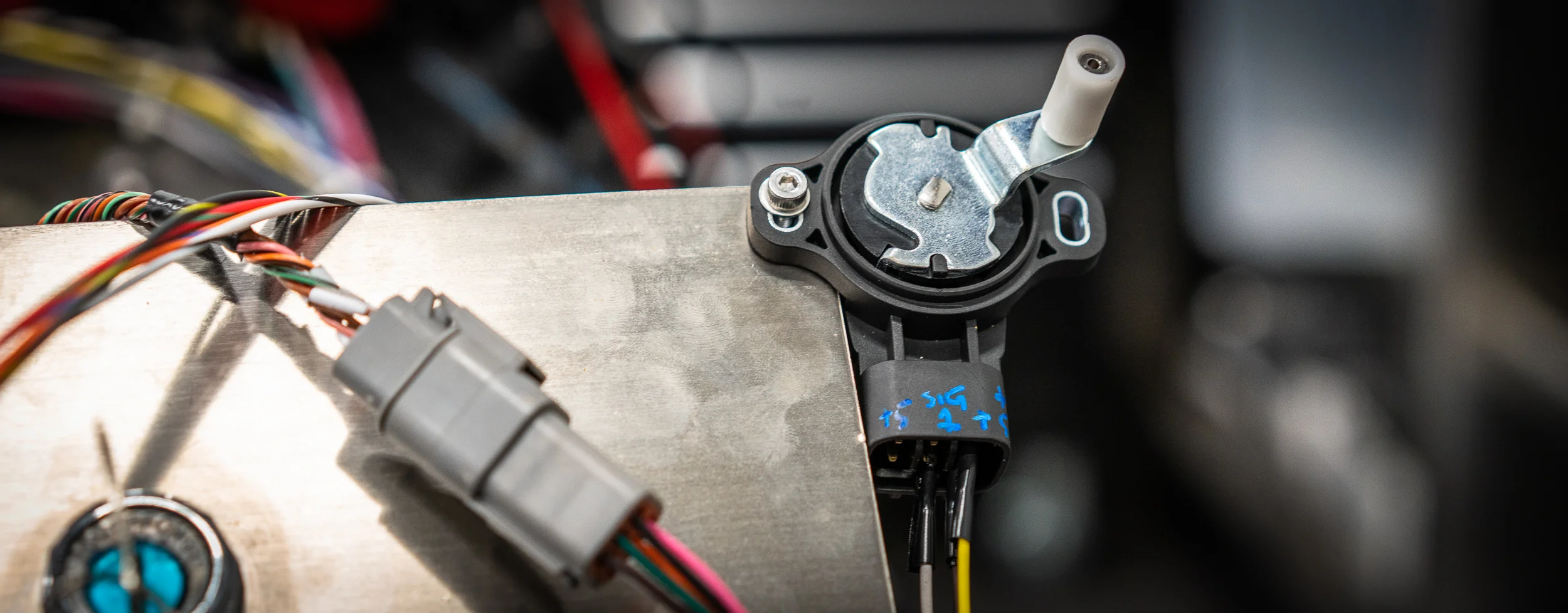
The part came in and I used my bench testing setup to figure out which pins did what. There were 6 pins. There are two sensors in the unit, each one with its own power, ground, and signal. I figured it out eventually and labeled the actual sensor housing with a paint pen and hooked up one of the sensors. I only need one signal for the ECU.
And here it is, bolted to the test stand, with the three wires hacked in.
With that last sensor sorted, I was ready to plug in the ECU and see what was what!
So I hooked up the USB cable from the AEM Infinity 708 ECU to my laptop and turned the key.
Connected!
The AEM uses a bunch of wizards to get started. I’m not a huge fan; they’re finicky and seem non-deterministic at times, losing configuration changes every now and then, etc. I’d rather just have tables to edit rather than drop-downs and abstracted controls.
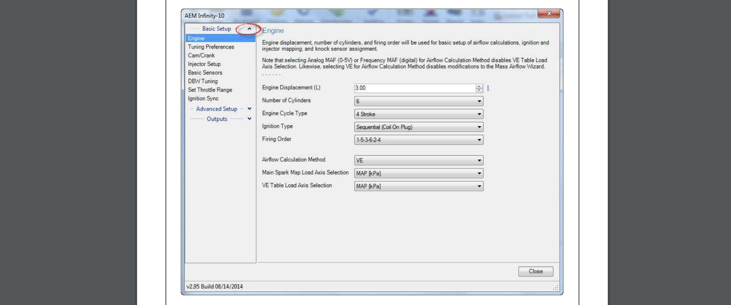
Here’s a shot of one of the main setup wizards from the AEM Infinity Quick Start-Up Manual:
There’s a wizard to setup the drive-by-wire system. It walks you through some steps where you hold the accelerator pedal open, then closed, then at 25%, and it opens and closes the throttle body, reading the feedback from the throttle body position sensor.
Then it’s supposed to use those first couple steps to do an auto-calibration on the electronic throttle body.
But it didn’t. It said, "Error, the throttle body signal did not change (changed less then .5v) ". Then it recommended I check my wiring.
Grrrr.
I could see that the throttle body position sensor was working correctly in the first three steps (there were some real-time gauges showing me the changes), so I thought maybe I had the motor wiring backwards, so I tried swapping those.
Beautiful, I know.
But that didn’t work either.
I had some time between shop days to email AEM’s support and scour the interwebz for a hint. AEM support never got back to me, but I did find a thread that talked about wiring up a drive-by-wire setup. They specifically mentioned having to wire up both sensors in the throttle body and both sensors in the accelerator pedal. I’d only done one of each.
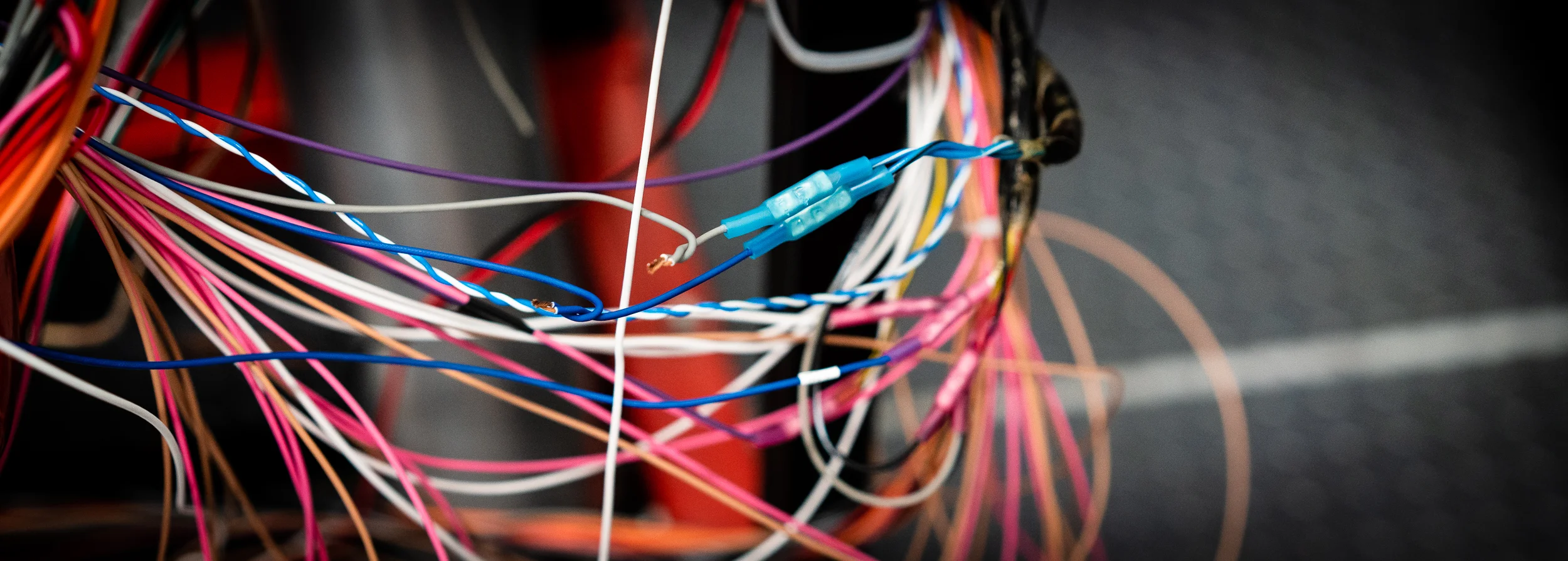
The next time I was out, I wired up the second sensor on both and this time, the calibration completed successfully! So anyone reading this in the future, you absolutely need 2 signals for actual throttle body position and 2 signals for the accelerator pedal position. From sources I’ve talked to since, it seems this is pretty standard; ECU manufacturers want to make sure there’s a backup for these two. Makes sense.
Okay, that meant I could crank it over to check for spark! I didn’t have any fuel hooked up yet. I figured it’d be easier to troubleshoot any spark problems first.
I’m glad I did that.
I tried using an inductive timing light that Nik had on the shelf, but I could not get it to flash. Either that meant I had no spark, or it meant I had the light hooked up incorrectly.
I first pulled the coil and plug out and cranked it while holding the plug against the block.
No spark from the actual plug.
I wanted to double check that the coil wasn’t generating voltage to the plug, so I came up with this convoluted (and admittedly not too safe) arrangement to try to get the light to show me something.
Imagine that, it didn’t work.
At this point I was pretty comfortable saying that the coil was not firing. None of them were.
I double checked the coil ground and power. They were good. Here’s the ground point on the back of the head:
I wasn’t seeing the crank trigger output in the ECU diagnostics tab either, which was strange. And probably one of the reasons I wasn’t getting spark.
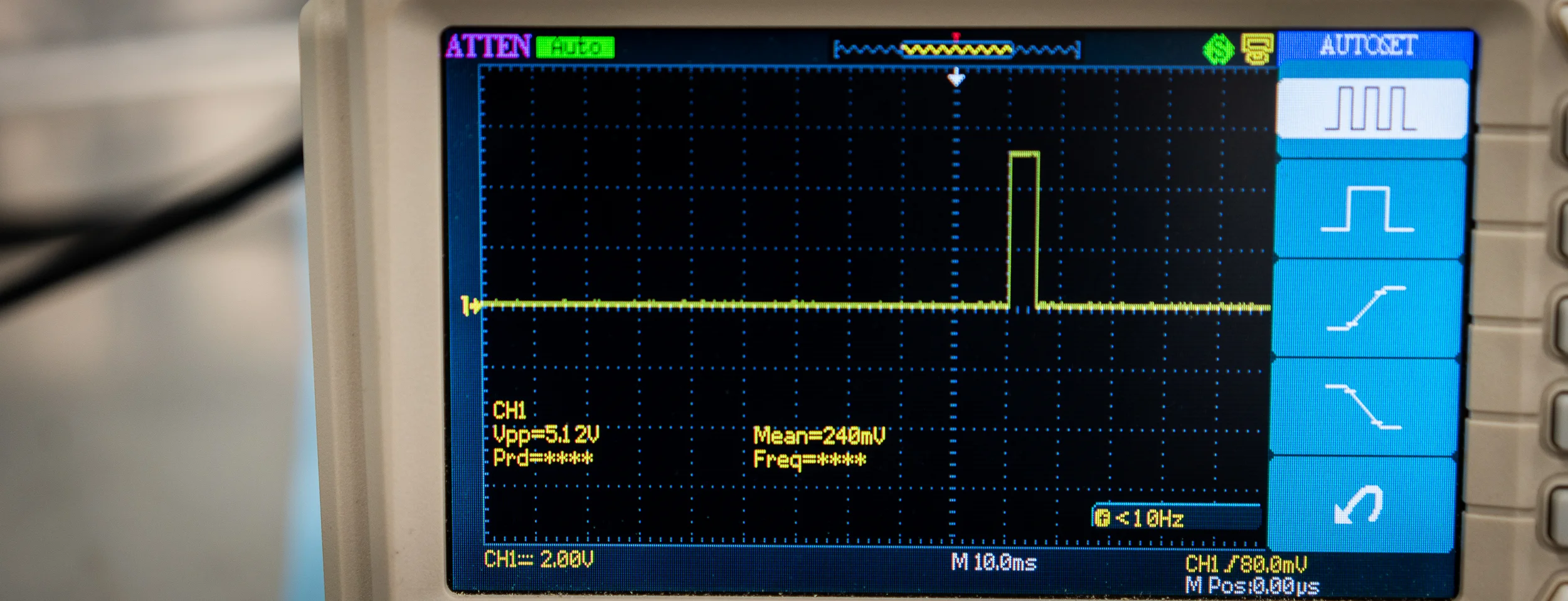
So I disconnected the DT plug for the crank sensor and checked the sensor side with the oscilloscope. It looked fine; I was getting a nice signal, just like before.
Well, when I went to reconnect the plug, I noticed the pins were awfully deep in the connector. Like too deep to be contacting the sockets. Sure enough, I got my pliers and pulled them into the right position, confirmed by a nice click. I had just done that wrong the first time.
Now the ECU was seeing the crank signal- woo!
But still no spark.
One thing that was rattling around in the back of my head was the cam trigger configuration. In order to run a fully sequential injection and spark setup, the ECU has to have a crank trigger signal as well as a cam trigger signal. I’ve seen a lot of talk on the AEM support forums about which trigger configurations are supported. I confirmed that my crank trigger (a 36-1 tooth wheel) was fine, but I was a bit concerned about the goofy Nissan cam trigger setup.
The documentation said that for universal applications (which is me, since they haven’t created firmware for my specific engine), the cam trigger must be one tooth only. Well, mine has 10 notches on the back in a I, III, II, IIII (yes 1, 3, 2, 4) at each 90 degrees. I guess that wasn’t going to work.
No problem though. AEM does have “Semi-Sequential” firmware that can work as long as you have a missing tooth on the crank trigger to tell the ECU where it’s at in the rotation. I have that. The difference is that the injectors will fire every revolution (for half as long), and the coils will fire every revolution (wasted spark). You actually don’t lose that much performance, so it certainly wouldn’t be a problem for my test on the stand.
So I loaded the semi-sequential firmware onto the ECU and re-did the configuration wizard.
Still no spark.
I confirmed that the ECU wasn’t sending a signal to the coil by hooking up the oscilloscope to the connector. Nope, no signal.
I emailed back and forth a bit with the AEM tech support. He went through some stuff with me, but what he was saying didn’t make a lot of sense regarding my application. He admitted to being limited help because my engine is not a supported application.
He did point me to their output testing firmware though. That was yet another firmware to load on the ECU that would allow me to manually trigger the outputs to the coil connectors to confirm that my wiring was correct. If I could confirm that, then I’d know I had a software configuration problem.
With the scope hooked up, I loaded the “Output Diagnostic Troubleshooting” firmware onto the ECU and triggered the coil output.
Behold! A signal!
That was actually great news, as it meant that my wiring harness was correct.
But it still didn’t tell me why I couldn’t get spark with the semi-sequential setup.
Just by chance, as I looked over the engine for inspiration, I remembered that the AEM tech mentioned to unplug the cam sensor when I loaded up the semi-sequential firmware. I sort of forgot that bit of advice as I assumed the semi-sequential firmware would ignore the cam sensor, since it wouldn’t be used.
I unplugged the cam sensor anyway.
AND IT WORKED. I CRANKED AND HAD SPARKS. WOOOO!!
It’s strange to me that AEM would still look at the cam sensor input in a semi-sequential setup, but apparently it was confusing the ECU enough to make it not sync. I haven’t been too pleased with the software on this ECU, but it’s early days. Maybe I’ll be more impressed with it later?
Anyhow, I could smell some whiffs of fuel being injected, which I’m sure was leftover in the rails, so it seemed the injectors were firing too.
That meant it was time to button up the last few things before I gave it a real crank attempt to start it up!
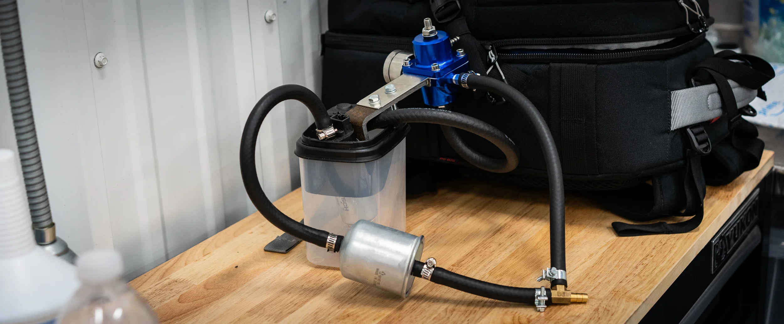
I did have a few minutes to put together my fuel pump, filter, regulator, and “tank” setup. I got a $13 adjustable fuel pressure regulator off eBay, an $8 filter, and a borrowed fuel pump from Nik. And some tupperware.
I present to you: a fueling setup to raise the hairs of professionals, fire marshals, and burn units everywhere.
I’m sure it’ll be fine. Right?
Thanks for reading!
damen
Next Datsun Post: Will It Start?
Previous Datsun Post: Wideband Sensors
All the Datsun Posts: 600 HP V8 Datsun 280Z Project
